January 22, 2002
Author: John Balestrieri
In order to test out algorithms that are meant to be part of a larger program, it helps to build small, isolated, test environments. Below are the first test images for an adaptive shadow subdivision algorithm to be used in a radiosity renderer.
A radiosity renderer calculates the light interactions between all of the surfaces, called patches, in a virtual 3d scene. When patch [i.e., surface] is detected to be partially in shadow, it needs to be broken up — or subdivided — in order to accurately represent the light/shadow that is falling across it’s surface.
Visualizing the progressive breakdown of a shadow patch is cumbersome to in an actually radiosity renderer — there are speed and data representation issues.
As an alternate solution, I saw a parallel between the bright/dark modulations of a black and white photograph with that of the light/shadow modulations across a single patch [i.e., surface] in a 3-dimensional. I am testing my code with 2d calculations rather than the 3d radiosity calculations which are much more complicated. Below is a photo of water lilies I took at the Brooklyn Botanic Garden which I am using as my standard test image.
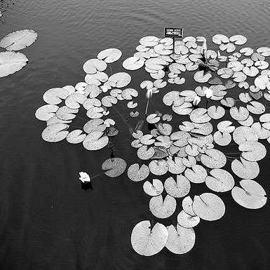
If the image below represents 1 patch in a 3-dimensional scene. The bright areas in the image represent light and the dark areas represent shadow. The red rectangles represent where the image has been subdivided [i.e., broken up]. You will notice that the subdivision occurs primarily in areas of high contrast; these are the borders between light and shadows.
The decision to subdivide a patch is controlled by stochastically [i.e., randomly] sampling sections of the image. First, a number of random samples are collected. Next, the samples are specially averaged. If that averaged value is detected to be above a specific threshold, that section of the image is subdivided and the process is repeated. Subdivision is terminated at a specific level/depth.
The goal is to develop a set heuristics that give the best possible representation of light/shadow in an image with the:
- Least amount of sampling
- Least amount of subdivision occurring at any given level
- Lowest possible level/depth of subdivision
- Highest possible subdivision threshold value
The actual values for the parameters are determined by experimentation and human evaluation of the output. Accuracy and speed are the simultaneous goals.
This image is probably representative of what an actually shadow would look like in a 3-dimensional scene rendered by the radiosity method.