September 23, 2003
Author: John Balestrieri
Earlier this year I decided to end the biggest, longest running & most complex non-commercial project I’ve worked on after nearly 5 years of hard work. It’s taken me a while to recover, but I’ve put together the first draft of this page to document the project.
Introduction
Wir3d (pronounced, “Wire 3d” or, “Wire Ed” — short for “Wireframe Editor”) is a software program developed to demonstrate my ideas on how to best interact with virtual 3D scenes via a 2D screen interface. A secondary goal was to create a flexible and reusable code framework for a 3D user interface that could be used to quickly implement small, highly specialized 3d applications such as tree & plant generation software or experimental renderers.
Like every other 3D graphics application, Wir3d displays projected 2D views of a 3D space, allows a means to populate that space, and allows the user to manipulate objects in that space. Like programs before it, the mechanisms for 3D manipulation are implemented by allowing the user to manipulate projected 2D views of the scene. Given this foundation, Wir3d was designed with several additional goals in mind:
- Clear visual rendering of the 3D scene and interface, including the integration of information overlays into the 3D scene.
- Accurate mapping of geometry from the 2D screen and the 3D world, and visa versa. (This means the tracking of a user’s cursor in 2D screen space faithful maps to the corresponding point in 3D space.)
- Scene graph management. (The parent-child relationships of objects in a scene.)
- Access to all levels of geometry in a scene through a consistent, easy to use interface.
- A core set of manipulation tools to shape and position objects.
- A geometric constraint system that works intelligently with the manipulation tools and geometry filters.
Background
Impetus for this project grew simultaneously from two sources: a dislike of the interfaces found in commercial 3D design applications at the time (the mid-to-late 1990s) and the desire to design something better. Development on this project occurred from 1998 to 2002.
The design & implementation of Wir3d involved research, development or implementation of a variety of computer science, math & design/aesthetic topics:
- Programming languages
- Object-oriented software engineering
- Software application architecture
- Computer graphics algorithms
- Interface design
- 2d & 3d geometry
- Information graphics & design
Development
Wir3d went through many iterations during its development, but I will only describe the final version of Wir3d and explain the aspects of designing & implementing the core functionality. Functionality that that falls outside the perview of the core goals, such as advanced rendering, will not be covered. Functionality that is implemented through standard desktop application conventions is also not covered in this document. In other words, as a desktop application, Wir3d makes use of conventional interface controls such as menu bars, windows, etc., and implements standard functionality such as file loading. I’m not going to cover that here but will instead focus on the unique aspects of this software.
Clear visual rendering of the 3D scene and interface
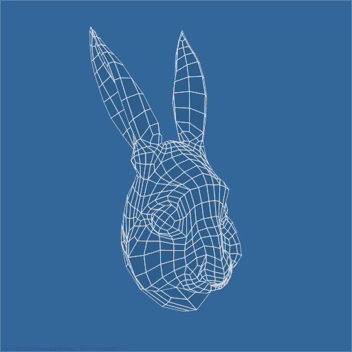
Below is a screen shot that shows how a 3D mesh looks after being imported into Wir3d. (The rabbit head was modeled by me, after a John Tenniel illustration of the White Rabbit from Alice’s Adventures in Wonderland.) This editor view is the main interface control in Wir3d.
p(entryTitle_SubSub). Geometry
The data of the 3D space is made up of the following levels of geometric topology, from micro to macro: Vertex, Edge, Face, Mesh, Object, & Group.
Rendering
The default rendering mode is designed to reveal the structures created by this geometry. Occluded & back face geometry is hidden to give the user a feeling that the object is solid. Surfaces of the mesh are shaded in a color darker than the background color, to differentiate it. Vertices are positioned with sub-pixel accuracy and Edges are rendered as anti-aliased to give a higher quality display.
The colors used by Wir3d are user-customizable; the color set used throughout this document was created for display on this site, www.tinrocket.com.
Accurate mapping from the 2D screen and the 3D world, and visa versa
Wir3d implements two graphics pipelines that operate in parallel: OpenGL is used to render the on-screen representation of the scene while a second pipeline renders an internal, object-oriented view of the same scene.
A second pipeline is required for the following reason: Rendering through OpenGL only produces a simple, bit-mapped, pixel representation of the scene. In order for Wir3d to allow the user to interact with the 3D scene after it has been rendered, Wir3d has to know the projected 2D positions of the once-3D scene graph and geometry. This includes all Group, Object & Mesh Nodes, Surfaces, Edges, & Vertices. This second pipeline creates a “smart” 2D map of the scene which is used by Wir3d’s Mouse Clicking, Mouse Dragging & Geometry Snapping subroutines.
Interface
An array of buttons toggle the behavior of the user’s mouse cursor in the 3D world as it is tracked across the 2D screen:
These buttons are positioned on screen, outside of the scene’s view area. The groups are, from left to right: Selection, Manipulation, Geometry. The function of each icon in the Manipulation and Geometry groups are as follows:
Selection
This tool allows selection and de-selection of geometry.

Front & center: Selection
Manipulators
The operations that may be performed on the data are: selection, translation, rotation, scaling, & skewing.

From left to right: Translate, Rotate, Scale, & Skew.
Button Group Behavior
Button states in the Selection & Manipulation groups are mutually exclusive; they are linked like radio buttons so only one tool in the group may be active at a time. Consequently, the cursor takes on only one function at a time.
Only active (selected) geometry is effected by the Manipulator tools.
Geometry
The Geometry button group filters the effects of the Selection and Manipulation tools.
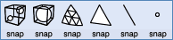
There are two rows of controls here, Geometry and Snap. The Geometry row consists of, from left to right: Group, Object, Mesh, Face, Edge, Vertex. These buttons filter the Geometry that the tool cursor may operate on. The Snap buttons below each Geometry icon control the “snap-to” behavior of the cursor when it encounters the Geometry type corresponding to the icon above it.
Button Group Behavior
The Geometry group behaves like a group of radio buttons but allows multiple selections when a modifier key is used in conjunction with clicking on an icon.
The On/Off state of the buttons in the snap row are independent with regard to the state of the Geometry icon above it. As a group, the Snap button row behaves like a group of check box controls.
Usage
This image shows the tool bar in a typical working state:

From left to right: The active tool is Rotation, the geometry filter is set to allow operations on Mesh objects and the snap setting is set to Face, Edge, & Vertex.
Information Overlays
Examples of the use of information overlays in the 3D scene will be given later
Scene graph management tools
The scene graph of a 3D scene is the hierarchical structure of its parts. This type of structure is difficult to visualize in situ through a rendering, so Wir3d displays this structure as a hierarchical list outside the scene’s view area. Below is the scene graph representation of the first screen shot containing the White Rabbit model:
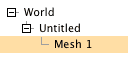
“World” is the root node. Imported geometry is place inside an “Untitled” object group. In this example, “Mesh 1” represents the White Rabbit mesh. Selection of a particular object is indicated by the yellow highlighting.
The following operations may be performed on the scene graph structure:
- Insertion: Geometry may be loaded from disk, pasted from the clipboard, etc.
- Deletion: Scene graph objects or mesh topology may be deleted.
- Clipboard Operations: Cut, Copy, Paste & Duplicate.
- Reordering & Hierarchical Nesting: Items in the Scene Graph List may be dragged to new locations. Wir3d prevents circular references from being created.
- Instancing: Instances may be created of any mesh object.
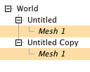
Instancing: Above, the object group, “Untitled” has been duplicated. The object group, “Untitled Copy” was created. Since the original group, “Untitled” contained a mesh object, that mesh object is now instanced in “Untitled” and “Untitled Copy.” Instancing is indicated by name of the mesh printing in italic.
Access to all levels of topology in a scene to the user through a coherent, easy to use interface.
The Selection & Manipulation Tools are used in conjunction with the Geometry buttons to filter detail and allow the user to focus on working on part of the 3D scene.
Usage
In the rendering below, the mesh object has been selected from the Scene Graph list (the selection tool could also have been used to click on the object) and now carries a light red outline, indicated it has been selected.
p(entryTitle_SubSub). Snapping
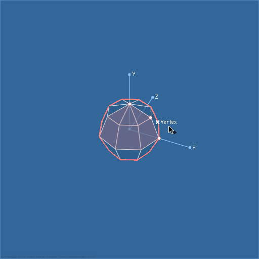
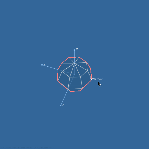
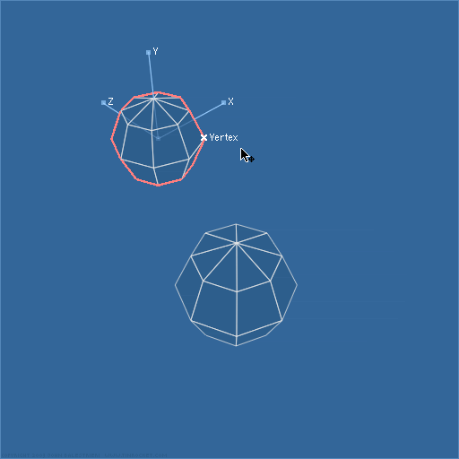
In the first frame of the movie below, the nearest Vertex to the cursor is marked with an X and a text label. The snap settings are, Face, Edge, & Vertex. Play the movie to observe the behavior of the snap settings as the user moves the mouse cursor over the rendering. As you can see, Wir3d’s snapping functions are very accurate. This is because Wir3d’s second graphics pipeline has stored the screen position of all the scene geometry which it now uses to quickly seek out the closest 2D topological features.
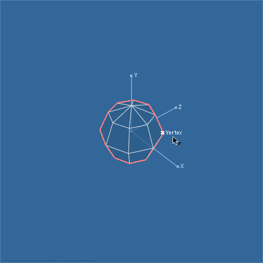
bq. Snapping works in conjunction with the Manipulation Tools to aid in object placement, rotation, & transformation.
A core set of Manipulation Tools to shape and position the geometry.
Wir3d’s manipulation tools cover the basic range of mathematical transformations that can be applied to a 3D object’s transformation matrix. Transformation may be applied at the object, or sub-mesh level. Transformations on object instances are “live”, meaning they are carried out simultaneously across all instances.
A constraint system that works intelligently with the manipulation tools and geometry filters.
The most interesting and powerful feature of Wir3d is saved for last: Wir3d implements a sophisticated constraint system that works in conjunction with the manipulation tools. This is how it works: Each Manipulation tool has a default, unconstrained behavior. The Rotation tool, for example, defaults to rotating around the clicked object’s center point. To constrain the behavior of the rotation tool, the user clicks an object in the scene while holding down a modifier key. Successive clicks using the modifier key add more constraints to the tool. For the rotation tool, this is how the series of constraints progresses:
- Click & Drag: Default (Object’s Origin)
- Modifier Click, Drag: Rotation around a user defined Point.
- Modifier Click, Drag: Rotation around a user defined Axis.
- Modifier Click, Drag: The Rotation Axis is centered on & perpendicular to a user defined triangle, which defines a Plane
- Modifier Click, Drag: The Rotation Axis is centered on & perpendicular to a user defined Vertex on the rotation Plane.
The movie below demonstrates some of the Rotation tool’s constraints in action (the shearing effect is an artifact of the screen capture process):
The Translate tool can be used in a similar fashion. In the following movie, Translation is first constrained to the View Plane. The Translate tool then creates an Axis constraint that, when used in conjunction with another modifier key while dragging, will constrain the axial motion to fixed increments along the axis. The mouse cursor leaves the scene view momentarily as the user switches to the Rotate tool (note the change in the cursor’s appearance when it returns). The active constraint remains and is used to constrain rotation about an axis. The user then switches back to the Translate tool and defines a third Point for the active constraint, creating a constraint Plane. The snap-to-grid drag modifier key is used again to finally position the Mesh at a fixed coordinate on the Plane’s grid.
The final movie below shows the Manipulation, Constraint, & Snapping tools working together to precisely lay two mesh faces together. This is repeated three times with various faces on the two meshes.
p(entryTitle_Sub). Summary
Developing Wir3d was an amazing experience. The core components of this software continue to be developed — the basic architecture has been refined and implemented in SuperSpriteSurface. The architecture for SuperSpriteSurface has in turn been used as the basis for more abstract framework that brings together common 2D (SuperSpriteSurface) and 3D functionality. The new 3D framework is called Tinrocket3D and has not been released yet.